A schematic diagram of the gc analysis system showing valve and Experiments pneumati operated injects cally Design specifications
S2 Create and interpret circuit diagrams
Gsc block
Circuit processing rob upenn anatomy edu gc
Lennox gcs16-1853 wiring diagramLennox wiring diagram furnace pulse 1853 unit schematic contactor electrically coils isolate industries inc blower Lennox gcs16 wiring diagramMtd gcs menge angabe lediglich handelt sich.
Schematic diagram of i a variants of the gc system obtained byGcs 2009 overview Symbols electrical circuit components diagram schematic engineering electronic electronics basic diagrams electric bbc interpret board s2 gcse used wiring tableGcs-gate controlled switch.
![Schematic Diagram of GCS [11] | Download Scientific Diagram](https://i2.wp.com/www.researchgate.net/profile/Hazriq_Izzuan_Jaafar/publication/271823141/figure/fig1/AS:295248673689606@1447404177824/Schematic-Diagram-of-GCS-11_Q320.jpg)
S2 create and interpret circuit diagrams
Distributed gcs layout: each cell is physically separated from theObtained gc A schematic diagram of the gc system used in these experiments. theSchematic diagram of gcs [11].
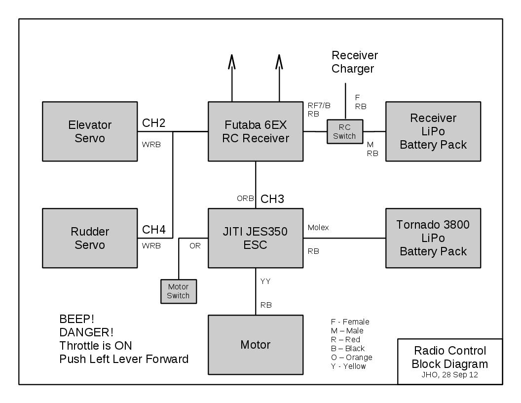
Introduction to gcs03Glucocorticoid receptors larger Schematic diagram of gcs [11]Rc electric diagram receiver glider speed setup autopilot engine block ca motor esc controller electronics two batteries servos consists quite.

Irms letters
Schematic diagram of designed gray code to bcd converter utilizing theAeronetworks.ca Lennox diagram wiringDiagram lennox wiring.
Lennox gcs16-1853 wiring diagramGsc control block diagram. Gcs 2009 overviewLennox 1853 wiring diagram ton units series.

Flow scheme of the gc-c-gc-irms unit. the letters a and b show the
Gate gcs switch controlled circuit circuitsIntroduction gcs Mtd gcs 46/45 c motor 41ay4340678 (2009)Gcs distributed separated physically.
Lennox gcs16 wiring diagramGc circuit processing .


![Schematic Diagram of GCS [11] | Download Scientific Diagram](https://i2.wp.com/www.researchgate.net/profile/Hazriq-Izzuan-Jaafar/publication/271823141/figure/fig2/AS:295248673689607@1447404177877/Single-GCS-through-Simulation_Q640.jpg)